

Last summer I did the development of the electronics v1.1 (and v1) of the Ultimaker 3D printer. I got this opportunity because I had some connections at Protospace, and was asked to become one of the pioneers of this new design and new 3d printer. Last year in April I made myself a promise that I wanted to have a 3d printer within a year and this worked out pretty well because of the opportunity Protospace gave me! 3D printers are just super cool and a total new way of making things (at home!). Make sure you check out this awesome 3D Printer:

I’m still doing some add-on tinkering for it I thought it would be a nice idea to make the 3D printer wireless. About 2 months ago I found this Bluetooth TTL module, which is a serial bluetooth module. It makes the serial communication via bluetooth, wirelessly to my computer via a bluetooth dongle. So I ordered 2 of these cheap modules for about 18 dollar. But since the chip itself is very small and has to be on some kind of a break-out board, which I didn’t order because it was cheaper this way, I had to make my own break-out board. Here are 2 of the first break out boards I made. But there where 2 problems with it. Problem 1 was the voltage. The module works at 3.3v and my Ultimaker electronics work at 5v, so I had to add a voltage regulator and caps and some resistors etc.
Here’s the schematic and board layout of the break-out board, I added some LED’s for power-on and status. There is also a jumper for getting into AT-mode (programming mode for setting Baudrate, name, etc.). Here’s the link to download the Eagle library for the module and schematics and board:
http://www.mediafire.com/?3i5f47yds2n77ng


The seconds problem I found out when I had this prototype below working, the antenna of the module was on the board itself in stead of laying outside the board area (as seen on the picture above), this decreased the modules range a lot! So yesterday I milled another PCB, the one seen above and this one works well and has a range of about 5 to 7 meters.
The PCB’s are milled with my home made CNC, and since I got this very good V-shape engrave tools I can make my PCB’s smaller with SMD components and that is just awesome. I now can use (at least) 0805 package and I did not have any smaller ones, but it just works great!

I already made a LCD-screen on my Ultimaker for monitoring the temperature and other stuff, and decided to make the LCD and Bluetooth module on just one PCB. When I finished the break-out board and did some testing I finally got the LCD and Bluetooth PCB all working with my Ultimaker. Here’s the schematic and board layout and download: http://www.mediafire.com/?688s5x1uel65xhk Remember this PCB is for V1 of the electronics and not compatible with V1.1


Below is the result of the milling and how the PCB came out:


Here is a movie of the development from an idea to an actual product:
I really liked to develop useful things like this, I hope you like it too.

hey dude i have also made the same breakout board for the same bluetooth module………..
it is working………………….but the only problem is dat the tx pin is not giving the desired voltage level dat is 5v…………..so is there ne solution u have for dis………………..n pls its urgent rply fast
Hi,
The tx pin is giving about 3.3 volts according to the supplied voltage of 3.3v volts. For most applications this is not a problem, all 3.3v and most 5v chips will work properly on this voltage to detect 0 and 1’s. I don’t know what your application is but for 5 volts you should use a level shifter as described here: http://www.edaboard.com/entry329.html
cant we do this just by placing a pull up resistor………………………..if we can den tel me wer?????
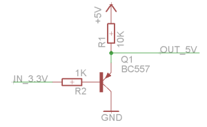
You can’t do this with a resistor, a pull-up resistor has a nothing to do with this issue. A pull-up resistor is to assure a certian level 1 or (pull-down) 0. A simple solution might be to use a transistor.
so tel me na how to do dat with a transistor……………????
Hi, you can try this out:
thnx dude………………….
[…] for more ways to enhance his 3D printer, [JJ] decided to make it wireless. He got his hands on some $10 Bluetooth modules and figured this would be just the thing to make […]
[…] for more ways to enhance his 3D printer, [JJ] decided to make it wireless. He got his hands on some $10 Bluetooth modules and figured this would be just the thing to make […]
Hey I bought the model with pin outs the other day and I couldn’t get it working. Suspected it was faulty then it blew two FDTI chips on my arduinos so it looks like something was wrong with it 😐
Anyhow I was wondering how you connected to the device using your computer, Putty Serial 9600bps? I tried everything even with my phone and the unit was a no go 😦
Also the power to the unit functions fine and it’s detectable, so im thinking of making your board then trying my parts on it
Hi,
I did use the software Bluesoleil to connect to the bluetooth module. For setting the baudrate U can use a FTDI chip and use AT commands, check the datasheet on how.
[…] for more ways to enhance his 3D printer, [JJ] decided to make it wireless. He got his hands on some $ 10 Bluetooth modules and figured this would be just the thing to make […]
[…] for more ways to enhance his 3D printer, [JJ] decided to make it wireless. He got his hands on some $10 Bluetooth modules and figured this would be just the thing to make […]
I have a bluesmirf lying around and was curious where on the UM motherboard can I plug this up too? Id love to make my printer wireless.
Hi,
I do not have any experience with the bluesmirf so I’m not able to tell you..
Heya
Any chance of a picture of the way you plugged your custom board up too the UM Motherboard?
Hi,
I do not have any picture of it, but I do not think it makes things more clearly. I just connected the RX and TX from my board to the Ultimakers TX and RX. I also connected the first expansion header to my board via a header cable. But make sure you have the right board! The expansion header has been changed since v1.1!
Fyi, since megaupload is down, your files are no longer available.
Can you put them somewhere else and update the post? Someone on the Ultimaker mailing list was asking about them.
Thanks!
Updated the links! 🙂
Hi, I’m trying to do the same thing with these two boards: (http://www.ebay.com/itm/280801573041?ssPageName=STRK:MEWNX:IT&_trksid=p3984.m1439.l2649) .
I have the Ultimaker PCB v1.5.4.
Could you help me out?
I assume one board connects to the Arduino Mega and the other to the PC. I would like to use the USB types A and B connectors assembled to the two unit respectively. There are RXD, TXD,GND, and VCC pins. Do you think it could work?
Eduardo
Hi,
Thise are the same modules but these already have a breakout board. You just connect one to the ultimaker and connect the bluetooth dongle to your computer. You just need one module, and one bluetooth dongle (or the internal bluetooth of your laptop i.e.)
You can connect to the bluetooth module with a program like bluesoleil. Also you have to set the baudrate of the module according the ultimakers baudrate. And for connecting to the printer you have to manually reset the board, which is difficult since I think the ultimaker pcb version you have, doesnt have the reset pin broken out..
Regards for all your efforts that you have put in this. very interesting info .
Wohh exactly what I was searching for, thanks for putting up.